what is a 2d drawing
2D drawing views
A 2D drawing view consists of two-dimensional elements. It is not associative to a 3D model. A 2D drawing view allows you to quickly create or modify a drawing view without making changes to a part or assembly document.
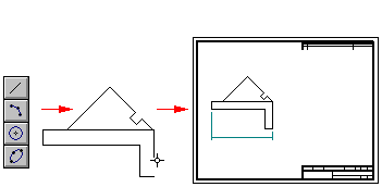
To create a 2D drawing view of a part or assembly, you can convert a 3D part view or you can draw the 2D graphics yourself. You also can import a 2D design file and then create 2D views from it. You can layer 2D graphics on top of a 2D view.
Whenever you add or edit 2D graphical elements, a full range of drawing tools is provided. These include drawing and relationship commands that make it easy for you to draw an accurate 2D representation of a part or assembly.

Note:
For more information about 2D drawing in Solid Edge, see the Drawing 2D elements Help topic.
2D model views
2D model views are scaled 2D drawing views placed on working sheets of geometry that reside at full scale on the 2D Model sheet. You can create multiple 2D model views that reference the 2D model geometry, and you can customize the cropping boundary for each view created from the geometry on the 2D Model sheet.
Creating a 2D drawing view
There are several commands related to creating a 2D view from existing graphics:
-
2D Model View command—Creates a 2D view that references geometry on the 2D Model sheet. Use the Drawing Area Setup command, which is available only for the 2D Model sheet, to set up a scaled work area in 2D model space.
-
Convert to 2D View command—Converts a 3D part view to 2D geometry. Once you convert a part view to a 2D view, associativity to the part or assembly document cannot be retrieved.
-
Draw In View command—Available for a 3D part, assembly, or sheet metal view placed on a working drawing sheet, this command opens a 2D View Edit window for you to draw in the view and to add annotations at a 1:1 scale.
-
2D View command—Superseded by the 2D Model View command, but still available through customization.
2D drawing scales
When drawing inside a 2D view placed on a working sheet, you typically work at 1:1 scale. You also can draw directly on the working sheet. If you decide later that you want to scale graphics you have drawn directly on the sheet, just move or copy them into a drawing view with the Cut, Copy, and Paste commands.
The dimension and annotation sizes on the working sheet are independent of the drawing view scale. For example, if you define the height and size of dimension text as 0.125 inches or 3.5 millimeters, these are the actual values of the dimension text on the printed drawing.

Using the 2D Model sheet
You also can work on the 2D Model sheet in 2D Model space. The Drawing Area Setup command defines a scaled work area where you can create, edit, and annotate a 2D design at a scale appropriate to the size of the part or assembly, yet print at a scale appropriate to the dimensions of your drawing sheet.
The Auto-Hide layer is available at all times when working on the 2D Model sheet.
2D Model view workflow
This workflow is used to create a 2D model view in a draft document.
First, use the 2D Model Sheet command to display the full-scale 2D Model sheet. There is one 2D Model sheet per document.
Next, use the Drawing Area Setup command to define a work space on the 2D Model sheet.
Next, place or create the design geometry on the 2D Model sheet, using any combination of design file import, dragging an existing .dft file onto the sheet, and 2D line drawing tools.
On the working drawing sheet, use the 2D Model View command to create one or more 2D model views that reference the 2D model geometry. You can customize the clipping boundary for each view created from the geometry on the 2D Model sheet, and assign a unique caption to each view.
Creating detail views from a 2D model view
You can use the Detail View command to create a dependent detail view from a 2D model view or a drawing view that has been converted to 2D geometry. You can create a detail view that displays a circular envelope or a detail view with a custom boundary.
Click here to learn more about Solid Edge detail views and the procedures for creating them.
2D views and associativity
If you set the Maintain Relationships option in the Relate group on the ribbon, the graphics you draw in a 2D view can be updated associatively, similar to the profiles you draw in the Part environment. You can place driving dimensions and apply relationships to control the size and location of the elements.

Hiding construction graphics, dimensions, and annotations
When you want to hide elements in a drawing view but you do not want to assign the hidden elements to individual layers, you can use the Auto-Hide layer. You can hide construction geometry, dimensions, and certain annotations. For example, you can place dimensions on the 2D Model sheet Auto-Hide layer to drive the size of the geometry but not display when a drawing view is placed on the working sheet.
-
The Auto-Hide layer is available while you are drawing and dimensioning on the 2D Model sheet. You can use the 2D Model View command
 to create a drawing view of the 2D Model sheet geometry, and all elements on the Auto-Hide layer are hidden automatically.
 -
The Auto-Hide layer also is created automatically when you right-click a drawing view and choose the Draw In View command. When you close a Draw In View window, elements on the Auto-Hide layer are hidden automatically.
Completing the 2D view
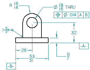
When you finish drawing in a 2D view on the working sheet, click the Return button on the command bar to close the 2D View Edit window. After you close the 2D view window, you can add driven dimensions and annotations, such as weld symbols, feature control frames, and so forth to the drawing sheet.
If you are working in 2D model space on the 2D Model sheet, you can add and edit annotations and dimensions directly on the sheet. The graphics you add on the 2D Model sheet are visible in the 2D view on the working sheet when you click the sheet tab.

Editing 2D views
When you need to edit 3D model graphics in a 2D view, double-click the view. You can also use the Draw in View command on the shortcut menu.
If the 2D view graphics were created from the 2D Model sheet as a block, or dragged onto the sheet as a file, then you can use the Open command on the shortcut menu to open the graphics for editing. Or you can use the Unblock command to drop the block to its base elements for individual manipulation.
If you created the 2D view associatively, you can edit the driving dimensions to modify the graphics. When you close the 2D view, the driven dimensions you placed on the sheet will update.

what is a 2d drawing
Source: https://www.soliddna.com/SEHelp/ST5/EN/a_h/dwg2v1a.htm
Posted by: boedingtorned1980.blogspot.com

0 Response to "what is a 2d drawing"
Post a Comment